Adding the Frames
Designing the frames
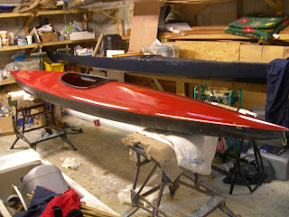
First of all the original Alacrity had to be redesigned; this was done right at the beginning before I fitted the new nose section shown in the previous post. Although I was happy with the original boat I thought that there were improvements that could be made:
Maximizing the volume, particularly in the stern had given this boat tumble-home in the quarter.
Plotting the Frames
The boat shown above was created on "Freeship" a marine architecture program that models hulls.
The outer dimensions of the frames can be exported from the program in the form of offsets. These are basically text documents with the dimensions of each slice of the hull represented as one of the vertical lines in the image above - only some of which will become frames. The Lowen was built by hand plotting on an A2 drawing board on to tracing paper which was then pricked out on to the plywood. This time I drew them out on "Turbo CAD". The plans were printed as shown below:
from an HP Photosmart 5510 inkjet - which will only do A4. As most images were A3 or larger the pages had to be taped together. The program gives the user lines to join them correctly. Some of the prints were out by about 1mm in their matching, which although well within the permissible error margin of about 3mm, was disconcerting. I think it was a problem with my printer as this did not show up on print shop copies.
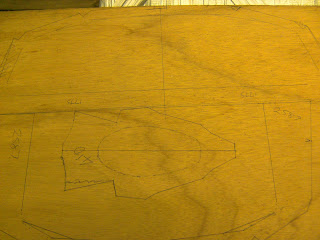
The pricked through shapes were outlined with biro:
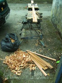
And then cut with a jigsaw:
Here I have utilized the space by putting one frame inside the other.
Then I did a quick line up of the frames in place to make sure I was somewhere about right before lashing them in.
First of all the original Alacrity had to be redesigned; this was done right at the beginning before I fitted the new nose section shown in the previous post. Although I was happy with the original boat I thought that there were improvements that could be made:
- The boat could be shortened; That long fine bow wasn't really necessary
- Better performance in a following sea - by increasing the volume under the quarter
- Higher top end speed through increasing the volume beneath the gunwales to give higher Prismatic Coefficient (the existing pinched plan of the gunwales was fixed)
- These changes incorporate the lessons learned in the last seven years since the original was built.
Plotting the Frames
The boat shown above was created on "Freeship" a marine architecture program that models hulls.
The outer dimensions of the frames can be exported from the program in the form of offsets. These are basically text documents with the dimensions of each slice of the hull represented as one of the vertical lines in the image above - only some of which will become frames. The Lowen was built by hand plotting on an A2 drawing board on to tracing paper which was then pricked out on to the plywood. This time I drew them out on "Turbo CAD". The plans were printed as shown below:
from an HP Photosmart 5510 inkjet - which will only do A4. As most images were A3 or larger the pages had to be taped together. The program gives the user lines to join them correctly. Some of the prints were out by about 1mm in their matching, which although well within the permissible error margin of about 3mm, was disconcerting. I think it was a problem with my printer as this did not show up on print shop copies.
The pricked through shapes were outlined with biro:
And then cut with a jigsaw:
Here I have utilized the space by putting one frame inside the other.
Then I did a quick line up of the frames in place to make sure I was somewhere about right before lashing them in.
Next Post: Securing the frames and footrest assembly.


Comments
Post a Comment