Cockpit, bulkheads and finishing off
Cockpit

It took longer to laminate the cockpit than one of the halves of the kayak. The complex shape was built up from many different pieces of chopped strand mat which all overlapped slightly. As the moulding was four layers thick, the laminating process had to be repeated that many times.
Furthermore it was difficult to wet out the narrow radius of the cockpit gutter and cuts had to be made in the edges of the mat being moulded round the back of the seat so that it would sit without creases. When it was clear that the creases would not come out I had to cut with Kevlar shears into the wet out mat so as to overlap. I was concerned that I might have ruined them, but they cleaned up nicely with acetone afterwards. Later I read that they could be used on wet out glass, or even cured laminate without harm.
Because of the length of time laminating outside on the hot day I used less than 1% catalyst. With the thickness of the laminate in places I was also worried about heat build up during curing but it was not a problem.


I used pieces of 3mm epoxied ply cut from the deck of a kayak I scrapped earlier this year on this prototype but would hope to mould them in GRP once I have committed to one design. As I prefer them to run at an angle to the hull to give less of a hard point on the bottom, the angled section can be difficult to plot.
I built up the shape with wood scraps and a glue gun as shown below:
 The outline rear bulkhead was easily plotted this way, and scribed onto plywood sheet.
 You do not need a great number of sticks and points to get a good idea of the shape. It does not matter if the fit is not perfect so long as the bulkhead is not forced in to create a hard spot in the hull. The gaps would be bridged by laminated glass-fibre which would put a flexible layer over the gap to seal and nothing more.
 After cutting with a jigsaw the panel was laminated in place first of all around the edges and then overlapped right across to give a nice stiff bulkhead.

 This was relatively straightforward to scribe shape and fit. However the bow bulkhead had to be made in two parts as it was so much more difficult to get at. Before being bolted together sections were plotted inside the two laminated halves of the kayak at the same distance from the bow - where the flanges were marked. The shapes were determined the same way as described in the preceding paragraph.
 This photo shows the bottom half of the bulkhead ready to go. The top half was then held in place with filler. Then the two halves were laminated into place and then joined when the lamination was taken across the whole bulkhead.
This was done with the boat upside down quite high up so that I could stand and reach down the hull.
 Ventilation was a big issue in this job and I had all the fans on as well as using a vacuum cleaner hose inside the cockpit.
In the event the resin did not set properly at the early stage of this process, so what could be removed was and about a week later the whole process repeated, this time successfully. By this time I had become quite concerned about the risk to my health by the poor ventilation in the workshop which is really a large garage with shelving and a good floor.
The footrest flanges had been plotted some time earlier as shown below. These were bonded to the deck so as to give a better foot position (I find it too low on the hull side of the join with the danger of the feet going over the top and jamming necessitating a fail safe or full plate unit). Although the deck is thinner and in theory weaker, the bonding is to the deck where it is reinforced by two layers of joining tape.

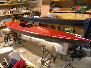
The cockpit needed a bit of fairing to go into its opening. There will be a photo of this in place in the next post which will also describe the maiden voyage etc.
Picture shows seat coated with PVA awaiting Gelcoat.

It took longer to laminate the cockpit than one of the halves of the kayak. The complex shape was built up from many different pieces of chopped strand mat which all overlapped slightly. As the moulding was four layers thick, the laminating process had to be repeated that many times.
Furthermore it was difficult to wet out the narrow radius of the cockpit gutter and cuts had to be made in the edges of the mat being moulded round the back of the seat so that it would sit without creases. When it was clear that the creases would not come out I had to cut with Kevlar shears into the wet out mat so as to overlap. I was concerned that I might have ruined them, but they cleaned up nicely with acetone afterwards. Later I read that they could be used on wet out glass, or even cured laminate without harm.
Because of the length of time laminating outside on the hot day I used less than 1% catalyst. With the thickness of the laminate in places I was also worried about heat build up during curing but it was not a problem.

Gelcoated mould clamped firmly in a Work-mate, CSM pieces ready for laminating in foreground.
Although four layers thick I was able to trim the edges successfully despite the resin being quite well set: hard work on the wrist with the Stanley knife and I went through a few blades. The rough edges needed sanding later. The completed cockpit and seat came out of the mould quite easily and the quality of the completed article was better than expected.
Newly "popped" seat cockpit in PVA skin.
BulkheadsI used pieces of 3mm epoxied ply cut from the deck of a kayak I scrapped earlier this year on this prototype but would hope to mould them in GRP once I have committed to one design. As I prefer them to run at an angle to the hull to give less of a hard point on the bottom, the angled section can be difficult to plot.
I built up the shape with wood scraps and a glue gun as shown below:


Photo, trial fit


This was done with the boat upside down quite high up so that I could stand and reach down the hull.

In the event the resin did not set properly at the early stage of this process, so what could be removed was and about a week later the whole process repeated, this time successfully. By this time I had become quite concerned about the risk to my health by the poor ventilation in the workshop which is really a large garage with shelving and a good floor.
The footrest flanges had been plotted some time earlier as shown below. These were bonded to the deck so as to give a better foot position (I find it too low on the hull side of the join with the danger of the feet going over the top and jamming necessitating a fail safe or full plate unit). Although the deck is thinner and in theory weaker, the bonding is to the deck where it is reinforced by two layers of joining tape.

Comments
Post a Comment