Frames and raised deck beams part 1
An earlier post showed the sheer of the gunwale on beams being measured with a laser level. In addition the widths of the frame were also measured at the station points (generally coinciding with deck beam positions), and adjustments made to the plan on the computer, and the offsets updated accordingly. The hull section outlines were then plotted on a drawing board from the offsets onto tracing paper (unlike the draft sections which were earlier plotted onto graph paper).

In order to finish the drawing, first of all the stringers need to be prepared, so that their dimensions can be drawn inside the section outlines, and then the actual shape of the frames drawn around them. I will be using wood-stock of 15 mm square in conjunction with 9 mm marine ply to construct the frames and this is drawn into the plans.
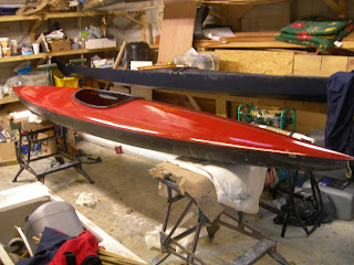
In parallel with this I laminated the main raised deck beam from ash - seen in the jig. Beyond that the completed hull stringers can be seen resting on the framework.


In order to finish the drawing, first of all the stringers need to be prepared, so that their dimensions can be drawn inside the section outlines, and then the actual shape of the frames drawn around them. I will be using wood-stock of 15 mm square in conjunction with 9 mm marine ply to construct the frames and this is drawn into the plans.
In parallel with this I laminated the main raised deck beam from ash - seen in the jig. Beyond that the completed hull stringers can be seen resting on the framework.


Comments
Post a Comment